Data Communications ICs
High-Level Serial Communication
Controller Extended (HSCX)
SAB 82525; SAB 82526
SAF 82525; SAF 82526
User’s Manual 10.94
�SAB 82525; SAF 82525; SAB 82526; SAF 82526
Revision History:
10.94
Previous Releases:
Page
01.92
Subjects (changes since last revision)
Update
Data Classification
Maximum Ratings
Maximum ratings are absolute ratings; exceeding only one of these values may cause irreversible damage to the integrated circuit.
Characteristics
The listed characteristics are ensured over the operating range of the integrated circuit. Typical
characteristics specify mean values expected over the production spread. If not otherwise
specified, typical characteristics apply at TA = 25 °C and the given supply voltage.
Operating Range
In the operating range the functions given in the circuit description are fulfilled.
For detailed technical information about “Processing Guidelines” and
“Quality Assurance” for ICs, see our “Product Overview”.
Edition 10.94
This edition was realized using the software system FrameMaker.
Published by Siemens AG, Bereich Halbleiter, Marketing-Kommunikation,
Balanstraße 73, D-81541 München
Siemens AG 1994. All Rights Reserved.
As far as patents or other rights of third parties are concerned, liability is only assumed for components , not for
applications, processes and circuits implemented within components or assemblies.
The information describes the type of component and shall not be considered as assured characteristics.
Terms of delivery and rights to change design reserved.
For questions on technology, delivery, and prices please contact the Offices of Semiconductor Group in Germany
or the Siemens Companies and Representatives worldwide (see address list).
Due to technical requirements components may contain dangerous substances. For information on the type in
question please contact your nearest Siemens Office, Semiconductor Group.
Siemens AG is an approved CECC manufacturer.
Packing
Please use the recycling operators known to you. We can also help you - get in touch with your nearest sales
office. By agreement we will take packing material back, if it is sorted. You must bear the costs of
transport.
For packing material that is returned to us unsorted or which we are not obliged to accept, we shall have
to invoice you for any costs incurred.
�General Information
Table of Contents
Page
1
Features ..................................................................................................................... 6
1.1
Pin Definitions and Functions ................................................................................... 10
1.2
System Integration .................................................................................................... 17
1.3
Functional Description .............................................................................................. 22
2
2.1
2.2
2.3
2.4
2.5
2.6
Operating Modes ..................................................................................................... 24
Auto-Mode (MODE: MDS1, MDS0 = 00) .................................................................. 24
Non-Auto Mode (MODE: MDS1, MDS0 = 01) .......................................................... 24
Transparent Mode 1 (MODE: MDS1, MDS0, ADM = 101) ....................................... 25
Transparent Mode 0 (MODE: MDS1, MDS0, ADM = 100) ....................................... 25
Extended Transparent Modes 0; 1 (MODE: MDS1, MDS0 = 11) ............................. 25
Receive Data Flow (Summary) ................................................................................. 26
2.7
Transmit Data Flow ................................................................................................... 27
3
3.1
3.2
3.3
Procedural Support (Layer-2 Functions) .............................................................. 28
Full-Duplex LAPB/LAPD Operation .......................................................................... 28
Half-Duplex SDLC-NRM Operation .......................................................................... 34
Error Handling ........................................................................................................... 38
4
4.1
4.2
4.3
4.4
4.5
CPU Interface .......................................................................................................... 38
Register Set .............................................................................................................. 38
Data Transfer Modes ................................................................................................. 38
Interrupt Interface ...................................................................................................... 39
DMA Interface ........................................................................................................... 43
FIFO Structure .......................................................................................................... 47
5
5.1
5.2
5.3
5.4
5.5
Serial Interface (Layer-1 Functions) ...................................................................... 49
Clock Modes .............................................................................................................. 49
Clock Recovery (DPLL) ............................................................................................ 57
Bus Configuration ..................................................................................................... 60
Data Encoding .......................................................................................................... 63
Modem Control Functions (RTS/CTS, CD) ............................................................... 63
6
6.1
6.2
6.3
6.4
6.5
6.6
Special Functions ................................................................................................... 65
Fully Transparent Transmission and Reception ....................................................... 65
Cyclic Transmission (Fully Transparent) ................................................................... 65
Continuous Transmission (DMA Mode only) ............................................................ 66
Receive Length Check Feature ................................................................................ 66
One Bit Insertion ....................................................................................................... 67
Data Inversion........................................................................................................... 67
Semiconductor Group
3
�General Information
Table of Contents
Page
6.8
Test Mode ................................................................................................................. 68
6.7
Special RTS Function ............................................................................................... 68
7
Operational Description ......................................................................................... 69
7.1
7.2
7.3
7.4
7.5
RESET ...................................................................................................................... 69
Initialization ............................................................................................................... 70
Operational Phase .................................................................................................... 71
Data Transmission .................................................................................................... 71
Data Reception ......................................................................................................... 75
8
8.1
8.2
Detailed Register Description................................................................................ 79
Register Address Arrangement ................................................................................. 79
Register Definitions ................................................................................................... 80
9
Electrical Characteristics ..................................................................................... 108
10
Quartz Specifications ........................................................................................... 118
11
Package Outlines .................................................................................................. 125
Semiconductor Group
4
�General Information
The SAB 82525 is a High-Level Serial Communication Controller compatible to the SAB 82520
HSCC with extended features and functionality (HSCX).
The SAB 82526 is pin and software compatible to the SAB 82525, realizing one HDLC channel
(channel B).
The HSCX has been designed to implement high-speed communication links using HDLC
protocols and to reduce the hardware and software overhead needed for serial synchronous
communications.
Due to its 8-bit demultiplexed adaptive bus interface it fits perfectly into every Siemens/Intel or
Motorola 8- or 16-bit microcontroller or microprocessor system. The data through-put from/to
system memory is optimized transferring blocks of data (usually 32 bytes) by means of DMA
or interrupt request. Together with the storing capacity of up to 64 bytes in on-chip FIFO’s, the
serial interfaces are effectively decoupled from the system bus which drastically reduces the
dynamic load and reaction time of the CPU.
The HSCX directly supports the X.25 LAPB, the ISDN LAPD, and SDLC (normal response
mode) protocols and is capable of handling a large set of layer-2 protocol functions
independently from the host processor.
Furthermore, the HSCX opens a wide area for applications which use time division multiplex
methods (e.g. time-slot oriented PCM systems, systems designed for packet switching, ISDN
applications) by its programmable telecom-specific features.
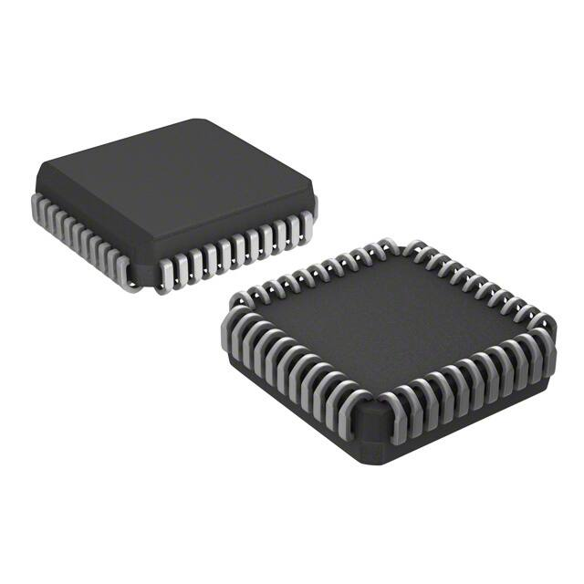
The HSCX is fabricated using Siemens advanced ACMOS 3 technology and available in a
P-LCC-44 pin package.
The data link controller handles all functions necessary to establish and maintain an HDLC
data link, such as
– Flag insertion and detection,
– Bit stuffing,
– CRC generation and checking,
– Address field recognition.
Associated with each serial channel is a set of independent command and status registers
(SP-REG) and 64-byte deep FIFO’s for transmit and receive direction.
DMA capability has been added to the HSCX by means of a 4-channel DMA interface
(SAB 82525) with one DMA request line for each transmitter and receiver of both channels.
General
Advanced CMOS technology
Low power consumption: active 25 mW at 4 MHz
standby 4 mW
Semiconductor Group
5
�SAB
SAB
SAF
SAF
High-Level Serial
Communications Controller Extended
(HSCX)
Preliminary Data
1
82525
82526
82525
82526
CMOS IC
Features
Serial Interface
Two independent full-duplex HDLC channels
(SAB 82526: one channel)
– On chip clock generation or external clock source
– On chip DPLL for clock recovery for each channel
– Two independent baudrate generators
(SAB 82526: one baudrate generator)
– Independent time-slot assignment for each channel
with programmable time-slot length (1-256 bit)
P-LCC-44-1
Different modes of data encoding
Modem control lines (RTS, CTS, CD)
Support of bus configuration by collision resolution
Programmable bit inversion
Transparent receive/transmit of data bytes
without HDLC framing
Continuous transmission of 1 to 32 bytes possible
Data rate up to 4 Mbit/s
P-MQFP-44-2
Type
Ordering Code
Package
SAB 82525 N
Q67100-H6486
P-LCC-44-1 (SMD)
SAB 82526 N
Q67100-H6512
P-LCC-44-1 (SMD)
SAF 82525 N
Q67100-H6504
P-LCC-44-1 (SMD)
SAF 82526 N
Q67100-H6511
P-LCC-44-1 (SMD)
SAB 82525 H
Q67101-H6482
P-MQFP-44-2 (SMD)
Semiconductor Group
6
10.94
�SAB
SAB
SAF
SAF
82525
82526
82525
82526
Features (cont’d)
Protocol Support
Various types of protocol support depending on operating mode
– Auto-mode
– Non-auto mode
– Transparent mode
Handling of bit oriented functions in all modes
Support of LAPB/LAPD/SDLC/HDLC protocol in auto-mode (I- and S-frame handling)
Modulo 8 or modulo 128 operation
Programmable time-out and retry conditions
Programmable maximum packet size checking
µP Interface
64 byte FIFO’s per channel and direction
Storage capacity of up to 17 short frames in receive direction
Efficient transfer of data blocks from/to system memory by DMA or interrupt request
8-bit demultiplexed or multiplexed bus interface
Intel or Motorola type µP interface
Semiconductor Group
7
�SAB
SAB
SAF
SAF
Pin Configurations
(top view)
RD/IC1
D7
D6
D5
D4
D3
D2
D1
D0
V DD
DRQTA
P-LCC-44
6 5 4 3 2 1 44 43 42 41 40
WR/IC0
CS
RxDA
RTSA
CTSA/CxDA
TxDA
TxDB
CTSB/CxDB
RTSB
RxDB
RES
7
8
9
10
11
12
13
14
15
16
17
HSCX
SAB 82525
SAF 85525
39
38
37
36
35
34
33
32
31
30
29
DRQRA
DRQTB
DRQRB
TxCLKA
RxCLKA
AxCLKA
RxCLKB
TxCLKB
AxCLKB
DACKA
DACKB
IM1
ALE/IM0
V SS
A6
A5
A4
A3
A2
A1
A0
INT
18 19 20 21 22 23 24 25 26 27 28
ITP00944
RD/IC1
D7
D6
D5
D4
D3
D2
D1
D0
VDD
N.C.
P-LCC-44
6 5 4 3 2 1 44 43 42 41 40
WR/IC0
CS
N.C.
N.C.
N.C.
N.C.
TxDB
CTSB/CxDB
RTSB
RxDB
RES
7
8
9
10
11
12
13
14
15
16
17
HSCX1
SAB 82526
SAF 82526
39
38
37
36
35
34
33
32
31
30
29
N.C.
DRQTB
DRQRB
N.C.
RxCLKA
AxCLKA
RxCLKB
TxCLKB
AxCLKB
N.C.
DACKB
IM1
ALE/IM0
V SS
A6
A5
A4
A3
A2
A1
A0
INT
18 19 20 21 22 23 24 25 26 27 28
Semiconductor Group
8
ITP00945
82525
82526
82525
82526
�SAB
SAB
SAF
SAF
Pin Configurations
(top view)
DRQRA
DRQTB
DRQRB
TxCLKA
RxCLKA
AxCLKA
RxCLKB
TxCLKB
AxCLKB
DACKA
DACKB
P-MQFP-44-2
1
2
3
4
5
6
7
8
9
10
11
44 43 42 41 40 39 38 37 36 35 34
33
32
31
30
29
HSCX
28
SAB 82525 H
27
26
25
24
23
12 13 14 15 16 17 18 19 20 21 22
WR/IC 0
CS
RxDA
RTSA
CTSA/CxDA
TxDA
TxDB
CTSB/CxDB
RTSB
RxDB
RES
DRQTA
VDD
D0
D1
D2
D3
D4
D5
D6
D7
RD/IC 1
Semiconductor Group
9
INT
A0
A1
A2
A3
A4
A5
A6
VSS
ALE/IM 0
IM 1
ITP05885
82525
82526
82525
82526
�SAB
SAB
SAF
SAF
82525
82526
82525
82526
1.1 Pin Definitions and Functions
Pin No.
Symbol
Input (I)
Output (O)
Function
Data Bus
P-LCC P-MQFP
42
43
44
1
2
3
4
5
3
4
5
6
7
8
9
10
D0
D1
D2
D3
D4
D5
D6
D7
I/O
6
11
RD/IC1
I
The data bus lines are bidirectional threestate lines which
interface with the system’s data bus.
These lines carry data and command/status to and from
the HSCX.
Read, Intel bus mode, IM1 connected to low
This signal indicates a read operation. When the HSCX is
selected via CS the read signal enables the bus drivers to
put data from an internal register addressed via A0-A6 on
the data bus.
When the HSCX is selected for DMA transfers via DACK,
the RD signal enables the bus driver to put data from the
respective receive FIFO on the data bus. Inputs to A0-A6
are ignored.
Input Control 1, Motorola bus mode IM1 connected to
high.
If Motorola bus mode has been selected this pin serves
either as
E = Enable, active high (IM0 tied to low) or
DS = Data Strobe, active low (IM0 tied to high)
input (depending on the selection via IM0) to control read/
write operations.
7
12
WR/IC0 I
Write, Intel bus mode
This signal indicates a write operation. When CS is active
the HSCX loads an internal register with data provided via
the data bus. When DACK is active for DMA transfers the
HSCX loads data from the data bus on the top of the
respective transmit FIFO.
Input Control Motorola bus mode
In Motorola bus mode, this pin serves as the R/W input to
distinguish between read or write operations.
8
13
CS
I
Chip Select
A low signal selects the HSCX for a read/write operation.
Semiconductor Group
10
�SAB
SAB
SAF
SAF
82525
82526
82525
82526
Pin Definitions and Functions (cont’d)
Pin No.
Symbol
Input (I)
Output (O)
Function
Receive Data (channel A/channel B)
P-LCC P-MQFP
9
16
14
21
RXDA
RXDB
I
10
15
15
20
RTSA
RTSB
O
Serial data is received on these pins at standard TTL or
CMOS levels.
Request to Send (channel A/channel B)
When the RTS bit in the mode register is set, the RTS
signal goes low. When the RTS is reset, the signal goes
high if the transmitter has finished and there is no further
request for a transmission.
In a bus configuration, this pin can be programmed via
CCR2 to:
– go low during the actual transmission of a frame shifted
by one clock period, excluding collision bits
– go low during the reception of a data frame
– stay always high (RTS disabled).
11
16
14
19
CTSA/
CXDA
CTSB/
CXDB
I
Clear to Send (channel A/channel B)
A low on the CTS inputs enables the respective transmitter.
Additionally, an interrupt may be issued if a state transition
occurs at the CTS pin (programmable feature). If no "Clear
To Send" function is required, the CTS inputs can be
connected directly to VSS.
Collision Data (channel A/channel B)
In a bus configuration, the external serial bus must be
connected to the respective C × D pin for collision
detection.
12
13
17
18
TXDA
TXDB
O
Transmit Data (channel A/channel B)
Transmit data is shifted out via these pins at standard TTL
or CMOS levels. These pins can be programmed to work
either as push-pull, or open drain outputs supporting bus
configurations.
17
22
RES
I
RESET
A high signal on this input forces the HSCX into the reset
state. The HSCX is in power-up mode during reset and in
power-down mode after reset. The minimum pulse width is
1.8 µs.
Semiconductor Group
11
�SAB
SAB
SAF
SAF
82525
82526
82525
82526
Pin Definitions and Functions (cont’d)
Pin No.
Symbol
Input (I)
Function
Output (O)
IM1
I
P-LCC P-MQFP
18
23
Input Mode 1
Connecting this pin to either VSS or VDD the bus interface can
be adapted to either Siemens/Intel or Motorola
environment.
IM1 = LOW:
IM1 = HIGH:
19
24
ALE/
IM0
I
Intel bus mode
Motorola bus mode
Address Latch Enable (Intel bus mode)
A high on this line indicates an address on the external
address/data bus, which will select one of the HSCX’s
internal registers. The address is latched by the HSCX with
the falling edge of ALE. This allows the HSCX to be directly
connected to a CPU with multiplexed address/data bus
compatible to SAB 82520 HSCC.
The address input pins A0-A6 must be externally
connected to the data bus pins (D0-D6 for 8-bit CPU’s, D1D7 for 16-bit CPU’s, i.e. multiply all internal register
addresses by 2).
This pin should be connected to high for a de-multiplexed
bus.
Input Mode 0, Motorola bus mode
In Motorola Bus Mode, the level at this pin determines the
function of the IC1 pin (see description of pin 6).
20
25
VSS
I
Ground
27
26
25
24
23
22
21
32
31
30
29
28
27
26
A0
A1
A2
A3
A4
A5
A6
I
Address Bus
Semiconductor Group
These inputs interface with seven bits of the system’s
address bus to select one of the internal registers for read
or write.
They are usually connected at A0-A6 in 8-bit systems or at
A1-A7 in 16-bit systems.
12
�SAB
SAB
SAF
SAF
82525
82526
82525
82526
Pin Definitions and Functions (cont’d)
Pin No.
Symbol
Input (I)
Function
Output (O)
INT
oD
P-LCC P-MQFP
28
33
Interrupt Request
The signal is activated, when the HSCX requests an
interrupt.
The CPU may determine the particular source and cause of
the interrupt by reading the HSCX’s interrupt status
registers. (ISTA, EXIR).
INT is an open drain output, thus the interrupt requests
outputs of several HSCX’s can be connected to one
interrupt input in a "wired-or" combination.
This pin must be connected to a pull-up resistor.
30
29
35
34
DACKA I
DACKB
DMA Acknowledge (channel A/channel B)
When low, this input signal from the DMA controller notifies,
the HSCX, that the requested DMA cycle controlled via
DRQxx (pins 37–40) is in progress, i.e. the DMA controller
has achieved bus mastership from the CPU and will start
data transfer cycles (either read or write).
Together with RD, if DMA has been requested from the
receiver, or with WR, if DMA has been requested from the
transmitter, this input works like CS to enable a data byte to
be read from or written to the top of the receive or transmit
FIFO of the specified channel.
If DACKn is active, the input on pins A0–A6 is ignored and
the FIFOs are implicitly selected.
If the DACKn signals are not used, these pins must be
connected to VDD.
34
31
39
36
AxCLK
A
AxCLK
B
Semiconductor Group
I
Alternative Clock (channel A/channel B)
These pins realize several input functions. Depending on
the selected clock mode, they may supply either a
– CD (= Carrier Detect) modem control or general purpose
input.
This pin can be programmed to functions as receiver
enable if the "auto start" feature is selected (CAS bit in
XBCH set). The state at this pin can be read from VSTR
register,
– or a receive strobe signal (clock mode 1)
– or a frame synchronization signal in time-slot oriented
operation mode (clock mode 5)
– or, together with RxCLK, a crystal connection for the
internal oscillator (clock mode 4, 6, 7, AxCLK A only).
13
�SAB
SAB
SAF
SAF
82525
82526
82525
82526
Pin Definitions and Functions (cont’d)
Pin No.
Symbol
P-LCC P-MQFP
36
32
41
37
Input (I)
Function
Output (O)
TxCLK A I/O
TxCLK B
Transmit Clock (channel A/channel B)
The functions of these pins depend on the programmed
clock mode, provided that the TSS bit in the CCR2 register
is reset. Programmed as inputs (if the TIO bit in CCR2 is
reset), they may supply either
– the transmit clock for the respective channel (clock
mode 0, 2, 6),
– or a transmit strobe signal (clock mode 1).
Programmed as outputs (if the TIO bit in CCR2 is set), the
TxCLK pins supply either the
– transmit clock of the respective channel which is
generated either
from the baudrate generator (clock mode 2, 6; TSS bit in
CCR2 set),
or from the DPLL circuit (clock mode 3, 7),
or from the crystal oscillator (clock mode 4)
– or a tristate control signal indicating the programmed
transmit time-slot (clock mode 5).
35
33
40
38
RxCLK A I
RxCLK B
Receive Clock (channel A/channel B)
The functions of these pins also depend on the
programmed clock mode. In each channel, RxCLK may
supply either
– the receive clock (clock mode 0)
– or the receive and transmit clock (clock mode 1, 5)
– or the clock for the baudrate generator (clock mode 2,
3),
– or a crystal connection for the internal
oscillator (clock mode 4,6,7, RxCLK A/B together
with AxCLK A)
39
37
44
42
DRQRA
DRQRB
Semiconductor Group
O
DMA Request Receiver (channel A/channel B)
The receiver of the HSCX requests a DMA data transfer by
activating this line.
The DRQRn remains high as long as the receive FIFO
requires data transfers, thus always blocks of data (32, 16,
8 or 4 bytes) are transferred.
DRQRn is deactivated immediately following the falling
edge of the last read cycle.
14
�SAB
SAB
SAF
SAF
82525
82526
82525
82526
Pin Definitions and Functions (cont’d)
Pin No.
Symbol
P-LCC P-MQFP
40
38
1
43
Input (I)
Output (O)
DRQTA O
DRQTB
Function
DMA Request Transmitter (channel A/channel B)
The transmitter of the HSCX requests a DMA data transfer
by activating this line.
The DRQTn remains high as long as the transmit FIFO
requires data transfers.
The amount of data bytes to be transferred from system
memory to the HSCX (= byte count) must be written first to
the XBCH, XBCL registers.
Always blocks of data (n x 32 bytes + REST, n = 0, 1,…)
are transferred till the byte count is reached.
DRQTn is deactivated immediately following the falling
edge of the last WR cycle.
41
2
VDD
Semiconductor Group
I
Power supply + 5 V.
15
�SAB
SAB
SAF
SAF
Channel A
A0-A6
SP-REG
LAP
Controller
Decoder
Collision
Detection
Transmit
FIFO
Data
Link
Controller
DPLL
D0-D7
RD/IC1
WR/IC0
CS
ALE/IMO
INT
82525
82526
82525
82526
µP Bus
Interface
Receive
FIFO
BRG
TSA
RxDA
TxDA
RTSA
CTSA/
CxDA
RxCLKA
Clock
Controll
AxCLKA
TxCLKA
RES
IM1
TxCLKB
DRQTA
AxCLKB
DRQRA
RxCLKB
DACKA
DMA
Interface
CTSB/
CxDB
DRQTB
RTSB
DRQRB
TxDB
DACKB
Channel B
RxDB
ITB00946
Figure 1
Block Diagram SAB 82525/SAB 82526
The HSCX SAB 82526 comprises one (channel B), the SAB 82525 two completely
independent full-duplex HDLC channels (channel A and channel B), supporting various layer-1
functions by means of internal oscillator, Baud Rate Generator (BRG), Digital Phase Locked
Loop (DPLL), and Time-Slot Assignment (TSA) circuits.
Furthermore, layer-2 functions are performed by an on-chip LAP (Link Access Procedure, e.g.
LAPB or LAPD) controller.
Semiconductor Group
16
�SAB
SAB
SAF
SAF
82525
82526
82525
82526
1.2 System Integration
General Aspects
CPU
Status
Memory
Command
Figure 2 gives a general overview of the system integration of HSCX.
INT
System Bus
CS
DRQTA, DRQRA, DACKA
DMA
Controller
DRQTB, DRQRB, DACKB
HSCX
DATA
Serial
Serial
Channel B Channel A
ITS00947
Figure 2
General System Integration of HSCX
The HSCX bus interface consists of an 8-bit bidirectional data bus (D0–D7), seven address
line inputs (A0–A6), three control inputs (RD/DS, WR/R/W, CS), one interrupt request output
(INT) and a 4-channel DMA interface (DRQTA, DRQRA, DACKA, DRQTB, DRQRB, DACKB).
Mode input pins (strapping options) allow the bus interface to be configured for either Siemens/
Intel or Motorola environment.
Generally, there are two types of transfers occurring via the system bus:
– command/status transfers, which are always controlled by the CPU. The CPU sets the
operation mode (initialization), controls function sequences and gets status information by
writing or reading the HSCX’s registers (via CS, WR or RD, and register address via A0-A6).
– data transfers, which are effectively performed by DMA without CPU interaction using the
HSCX’s DMA interface (DMA mode). Optionally, interrupt controlled data transfer can be
done by the CPU (interrupt mode).
Semiconductor Group
17
�SAB
SAB
SAF
SAF
82525
82526
82525
82526
Specific Applications
HSCX with SAB 8051 Microcontroller
For cost-sensitive applications, the HSCX can be interfaced with a small SAB 8051
microcontroller system (without DMA support) very easily as shown in figure 3.
+5 V
SAB 8051
CPU
INT0
RD
WR
ALE
+5 V
DACKA
DACKB
INT
RD
WR
ALE
SAB 82525
CS
HSCX
RD
WR
ALE
A8 - A15
Channel B
A0 - A6
D0 - D7
AD0 - AD7
A8 - A15
AD0 - AD7
Channel A
IM1
Latch
A0 - A15,D0 - D7
Common Bus
Memory
ITS00948
Figure 3
HSCX with 8051 CPU
Although the HSCX provides a demultiplexed bus interface, it can optionally be connected
directly to the local multiplexed bus of SAB 8051 because of the internal address latch function
(via ALE, compatibility to SAB 82520 HSCC).
The address lines A0 … A6 must be wired externally to the data lines D0 … D6 (direct
connection) in this case.
Intel bus mode is selected connecting IM1 pin to low ( VSS). Since data transfer is controlled by
interrupt, the DMA acknowledge inputs (DACKA, DACKB) are connected to VDD (+ 5 V).
Semiconductor Group
18
�SAB
SAB
SAF
SAF
82525
82526
82525
82526
HSCX with SAB 80188 Microprocessor
A system with minimized additional hardware expense can be with a SAB 80188
microprocessor as shown in figure 4.
+5 V
INTn
PSCn
DRQ0
CS
DRQTA
DRQ1
DRQRA
SAB 80188
CPU
DACKA
IM1
SAB 82525
HSCX
ALE
+5 V
Serial
Channel A
Serial
Channel B
DACKB
A8 - A15
AD0 - AD7
Latches
INT
A0 - A6
D0 - D7
A0-A6
D0-D7
Transceiver
System Bus
System
Memory
ITS00949
Figure 4
HSCX with SAB 80188 CPU
The HSCX is connected to the demultiplexed system bus. Data transfer for one serial channel
can be done by the 2-channel on-chip DMA controller of the SAB 80188, the other channel is
serviced by interrupt. Since the SAB 80188 does not provide DMA acknowledge outputs, data
transfer from/to HSCX is controlled via CS, RD or WR address information (A0 … A6) and the
DACKA, DACKB inputs are not used.
This solution supports applications with a high speed data rate in one serial channel with
minimum hardware expense making use of the on-chip peripheral functions of the SAB 80188
(chip select logic, interrupt controller, DMA controller).
Semiconductor Group
19
�SAB
SAB
SAF
SAF
82525
82526
82525
82526
HSCX with SAB 80186 Microprocessor
and SAB 82258 Advanced DMA Controller (ADMA)
In applications, where two high-speed channels are required, a 16-bit system with SAB 80186
CPU and SAB 82258 ADMA is suitable. This is shown in figure 5.
+5 V
INTn
HOLD
SAB 80186
CPU
AD0 - AD15
Latches
CS
DRQTA
DRQRA
PSCn
HLDA
S0 - S2
Transceiver
SAB 82258
ADMA
AD0 - AD15
DREQ0
DREQ1
DACK0
DACK1
DREQ2
DREQ3
DACK2
DACK3
S0 - S2
DACKA
IM1
Serial
Channel A
SAB 82525
DRQTB HSCX
DRQRB
&
Serial
Channel B
DACKB
A0 - A6
D0 - D7
A0 - A6
D0 - D7
Bus
Control
System Bus
System
Memory
Figure 5
HSCX with SAB 80186 CPU/SAB 82258 ADMA
Semiconductor Group
&
INT
20
ITS00950
�SAB
SAB
SAF
SAF
82525
82526
82525
82526
The four selector channels of ADMA are used for serving the four DMA request sources of
HSCX, allowing very high data rates at both the system bus and the serial channels.
Another big advantage of the ADMA is it’s data chaining feature, providing an optimized
memory management for receive and transmit data. Recording the HSCX, a linked chain of 32
byte deep buffers can be set up, which are subsequently filled with the contents of the HSCX’s
FIFOs during reception. Not used buffers can be saved and linked to another buffer chain
reserved for the reception of the next frame.
As a result, it’s not necessary to reserve a very large space in system memory, determined by
the maximum frame length of every received frame.
In this example, the ADMA works directly at the CPU’s local bus and shares the same bus
interface logic (address latches, transceivers, bus controller) with the SAB 80186. Since one
DMA acknowledge line is provided for each DMA request, two DACK outputs must be ANDed
together for input to the HSCX.
The HSCX’s data lines are connected to the lower half of the system data bus (D0 … D7) and
the address lines to A1 … A7, thus (from the CPU’s point of view) all internal register
addresses must be multiplied by two (even register addresses only).
e.g. CMDR register: HSCX address 61H < = > system address C2H.
1.3 Functional Description
General
The HSCX distinguishes from other low level HDLC devices by its advanced characteristics.
The most important are:
Enlarged support of link configurations.
Beyond the point-to-point configurations, the HSCX directly enables point-to-multipoint or
multimaster configurations without additional hardware or software expense.
In point-to-multipoint configurations, the HSCX can be used as a master as well as a slave
station. Even when working as slave station, the HSCX can initiate the transmission of data at
any time. An internal function block provides means of idle and collision detection and collision
resolution, which are necessary if several stations start transmitting simultaneously.
These features were integrated to support multimaster configurations.
Semiconductor Group
21
�SAB
SAB
SAF
SAF
82525
82526
82525
82526
Point-to-Point Configuration
TxD
TxD
RxD
RxD
HSCX
HSCX
Controller
Controller
ITC02705
RxD - Receive Data
Controller
TxD - Transmit Data
Master
HSCX
Point-to-Multipoint Configuration
TxD RxD
CxD TxD RxD
CxD TxD RxD
CxD TxD RxD
CxD TxD RxD
HSCX
HSCX
HSCX
HSCX
Slave 1
Controller
Slave 2
Slave 3
Controller
Slave n
Controller
Controller
ITC02694
RxD - Receive Data
CxD - Collision Data
TxD - Transmit Data
Multimaster Configuration
CxD TxD RxD
CxD TxD RxD
CxD TxD RxD
CxD TxD RxD
HSCX
HSCX
HSCX
HSCX
Master 1
Controller
Master 2
Master 3
Controller
Controller
Master n
Controller
ITC02695
RxD - Receive Data
CxD - Collision Data
TxD - Transmit Data
Figure 6
Link Configuration
Semiconductor Group
22
�SAB
SAB
SAF
SAF
82525
82526
82525
82526
Support of layer-2 functions by HSCX
Beside those bit-oriented functions usually supported with the HDLC protocol, such as bit
stuffing, CRC check, flag and address recognition, the HSCX provides a high degree of
procedural support. In a special operating mode (auto-mode), the HSCX processes the
information transfer and the procedure handshaking (I-, and S-frames of HDLC protocol)
autonomously. The only restriction is, that the window size (= number of outstanding
unacknowledged frames) is limited to 1, which will be sufficient in most applications. The
communication procedures are mainly processed between the communication controllers and
not between the processors. Thus the dynamic load of the CPU and the software expense is
largely reduced.
µP
HSCX
HSCX
µP
S Frame
I Frame
U Frame
ITS05502
Figure 7
Procedural Support in Auto-Mode
The CPU is informed about the status of the procedure and has to manage the receive and
transmit data mainly. In order to maintain cost effectiveness and flexibility, such functions as
link setup/disconnection and error recovery in case of protocol errors (U-frames of HDLC
protocols) are not implemented in hardware and must be done by user’s software.
Telecom specific features
In a special operating mode, the HSCX can transmit or receive data packets in one of up to 64
time-slots of programmable width (clock mode 5). Furthermore, the HSCX can transmit or
receive variable data portions within a defined window of one or more clock cycles, which has
to be selected by an external strobe signal (clock mode 1). These features make the HSCX
especially suitable for all applications using time division multiplex methods, such as time-slot
oriented PCM systems, systems designed for packet switching, or in ISDN applications.
FIFO buffers to efficient transfer of data packets.
A further speciality of HSCX are the FIFO buffers used for the temporary storage of data
packets transferred between the serial communications interface and the parallel system bus.
Also because of the overlapping input/output operation (dual-port behaviour), the maximum
message length is not limited by the size of the buffer. Together with the DMA capability, the
dynamic load of the CPU is drastically reduced by transferring the data packets block by block
via direct memory access. The CPU only has to initiate the data transmission by the HSCX and
determine the status in case of completely received frames, but is not involved in data
transfers.
Semiconductor Group
23
�SAB
SAB
SAF
SAF
2
82525
82526
82525
82526
Operating Modes
The HDLC controller of each channel can be programmed to operate in various modes, which
are different in the treatment of the HDLC frame in receive direction. Thus, the receive data
flow and the address recognition features can be effected in a very flexible way, which satisfies
most requirements.
There are 6 different operating modes which can be set via the MODE register.
2.1 Auto-Mode (MODE: MDS1, MDS0 = 00)
Characteristics: Window size 1, arbitrary message length, address recognition.
The HSCX processes autonomously all numbered frames (S-, I-frames) of an HDLC
procedure.
The HDLC control field, data in the I-field of the frames and an additional status byte is
temporarily stored in the RFIFO. The HDLC control field as well as additional information can
also be read from special registers (RHCR, RSTA).
According to the selected address mode, the HSCX can perform a 2-byte or 1-byte address
recognition. If a 2-byte address field is selected, the high address byte is compared with the
fixed value FEH or FCH (group address) as well as with two individually programmable values
in RAH1 and RAH2 registers. According to the ISDN LAPD protocol, bit 1 of the high byte
address will be interpreted as COMMAND/RESPONSE bit (C/R), dependent on the setting of
the CRI bit in RAH1, and will be excluded from the address comparison.
Similary, two compare values can be programmed in special registers (RAL1, RAL2) for the
low address byte. A valid address will be recognized in case the high and low byte of the
address field correspond to one of the compare values. Thus, the HSCX can be called
(addressed) with 6 different address combinations, however, only the logical connection
identified through the address combination RAH1, RAL1 will be processed in the auto-mode,
all others in the non-auto mode. HDLC frames with address fields that do not match with any
of the address combinations, are ignored by the HSCX.
In case of a 1-byte address, RAL1 and RAL2 will be used as compare registers. According to
the X.25 LAPB protocol, the value in RAL1 will be interpreted as COMMAND and the value in
RAL2 as RESPONSE.
After receiving a frame it takes 5 clock cycles to generate the response frame and to start
transmission.
2.2 Non-Auto Mode (MODE: MDS1, MDS0 = 01)
Characteristics: address recognition, arbitrary window size.
All frames with valid addresses (address recognition identical to auto-mode) are forwarded
directly to the system memory.
The HDLC control field, data in the I-field and an additional status byte are temporarily stored
in the RFIFO. The HDLC control field and additional information can also be read from special
registers (RHCR, RSTA).
In non-auto mode, all frames are treated similarly.
Semiconductor Group
24
�SAB
SAB
SAF
SAF
82525
82526
82525
82526
2.3 Transparent Mode 1 (MODE: MDS1, MDS0, ADM = 101)
Characteristics: address recognition high byte
Only the high byte of a 2-byte address field will be compared. The whole frame except the first
address byte will be stored in RFIFO. RAL1 contains the second and RHCR the third byte
following the opening flag.
2.4 Transparent Mode 0 (MODE: MDS1, MDS0, ADM = 100)
Characteristics: no address recognition
No address recognition is performed and each frame will be stored in the RFIFO. RAL1
contains the first and RHCR the second byte following the opening flag.
2.5 Extended Transparent Modes 0; 1 (MODE: MDS1, MDS0 = 11)
Characteristics: fully transparent
In extended transparent modes, fully transparent data transmission/reception without HDLC
framing is performed, i.e. without FLAG generation/recognition, CRC generation/check, bitstuffing mechanism. This allows user specific protocol variations or the usage of Character
Oriented Protocols (such as IBM BISYNC).
Data transmission is always performed out of the XFIFO. In extended transparent mode 0
(ADM = 0), data reception is done via the RAL1 register, which always contains the actual data
byte assembled at the RxD pin. In extended transparent mode 1 (ADM = 1), the receive data
are additional shifted into the RFIFO.
Also refer to chapter 6.1 and 6.2.
Semiconductor Group
25
�SAB
SAB
SAF
SAF
82525
82526
82525
82526
2.6 Receive Data Flow (Summary)
The following figure gives an overview of the management of the received HDLC frames as
affected by different operating modes.
FLAG
MDS1 MDS0 ADM MODE
ADDR
CTRL
ADDRESS
CONTROL
RAH1, 2 RAL1, 2
Ι
CRC
DATA
FLAG
STATUS
RFIFO
0
0
1
Auto/16
RHCR
RAL1, 2
0
0
0
1
1
RHCR
1
0
RSTA
RAL1, 2
RFIFO
Non
Auto/16
RHCR
RAL1, 2
0
RFIFO
Auto/8
RAH1, 2
0
X
RSTA
X
RSTA
RFIFO
Non
Auto/8
RHCR
RSTA
RAH1, 2
RFIFO
1
0
1
Transparent 1
RAL1
RHCR
RSTA
RFIFO
1
0
0
Transparent 0
RAL1
RHCR
ITD00228
Description of Symbols:
Compared with (register)
Processed autonomously
Note: In case of on 8 Bit Address,
the Control Field starts here!
Stored (FIFO, register)
Figure 8
Receive Data Flow of HSCX
Semiconductor Group
RSTA
26
�SAB
SAB
SAF
SAF
82525
82526
82525
82526
2.7 Transmit Data Flow
Two different types of frames can be transmitted:
– I-frames and
– transparent frames
as shown below.
FLAG
ADDR
CTRL
ADDRESS
CONTROL
Transmit
Transparent
Frame
(XTF)
Transmit
I-Frame
(XIF)
Ι
CRC
DATA
XFIFO
XAD2
CHECKRAM
*1
XFIFO
XAD1
FLAG
*1
ITD00229
*1 Optional checkram handling in version 2 upward
Figure 9
Transmit Data Flow of HSCX
For I-frames (command XIF via CMDR register), the address and control fields are generated
autonomously by the HSCX and the data in the XFIFO is entered into the information field of
the frame. This is possible only, if the HSCX is operated in the auto-mode.
For transparent frames (command XTF via CMDR register), the address and the control fields
have to be entered in the XFIFO as well. This is possible in all operating modes and used also
in auto-mode for sending U-frames.
Semiconductor Group
27
�SAB
SAB
SAF
SAF
3
82525
82526
82525
82526
Procedural Support (Layer-2 Functions)
When operating in the auto-mode, the HSCX offers a high degree of procedural support. In
addition to address recognition, the HSCX autonomously processes all (numbered) S- and
I-frames (prerequisite window size 1) with either normal or extended control field format
(modulo 8 or modulo 128 sequence numbers – selectable via RAH2 register).
The following functions will be performed:
– updating of transmit and receive counter
– evaluation of transmit and receive counter
– processing of S commands
– flow control with RR/RNR
– generation of responses
– recognition of protocol errors
– transmitting of S commands, if acknowledgement is missing
– continuous status query of opposite termination after RNR has been received
– programmable timer/repeater functions.
In addition, all unnumbered frames are forwarded directly to the processor.
Additional logic connections can be operated in parallel by software. The logic link can be
initialized by software at any time (RHR).
3.1 Full-Duplex LAPB/LAPD Operation
Initially (i.e. after RESET), the LAP controllers of the two serial channels are configured to
function as a combined station, where they autonomously perform a subset of the X.25 LAPB/
ISDN LAPD protocol.
Reception of Frames
The logic processing of received S-frames is performed by the HSCX without interrupting the
µC. The µC is merely informed by interrupt with respect to status changes in the opposite
station (receive ready/not receive ready) and protocol errors (unacceptable N(R) or S-frame
with I field).
I-frames are also processed autonomously and checked for protocol errors. The I-frame will
not be accepted in the case of N(s) error (no interrupt is forwarded to the µC), but is
immediately confirmed by an S response. If the µC sets the HSCX into a "receive not ready"
status, an I-frame will not be accepted (no interrupt) and an RNR response is transmitted.
U-frames are always stored in the RFIFO and forwarded directly to the µC. The logic sequence
and the reception of a frame in the auto-mode is illustrated in figure 10.
Note: The state variables N(S), N(R) are evaluated within the window size, i.e. the HSCX
checks only the Isb of the receive and transmit counter regardless of the selected
modulo count.
Semiconductor Group
28
�SAB
SAB
SAF
SAF
82525
82526
82525
82526
Transmission of Frames
The HSCX autonomously transmits S commands and S responses in the auto-mode. Either
transparent or I-frames can be transmitted by the user. The software timer has to be operated
in the internal timer mode to transmit I-frames. After the frame has been transmitted, the timer
is self-started, the XFIFO is inhibited, and the HSCX waits for the arrival of a positive
acknowledgement. This acknowledgement can be provided by means of an S- or I-frame.
If no positive acknowledgement is received during time t1, the HSCX transmits an S command
(p = 1), which must be followed by an S response (f = 1). If the S response is omitted, the
process is performed n1 times before it is terminated.
Upon the arrival of an acknowledgement or after the completion of this poll procedure the
XFIFO is enabled and an interrupt is forwarded to the µC. Interrupts may be triggered by the
following:
– message has been acknowledged as positive (XPR interrupt)
– message must be repeated (XMR interrupt)
– response has not been received (TIN interrupt)
Upon arrival of an RNR frame, the software timer is started and the status of the opposite
station is polled periodically after expiration of t1, until the status "receive ready" has been
detected. The user is informed accordingly via interrupt. If no response is received after n1
times an interrupt will be generated (TIN interrupt). As a result, the process will be terminated
as illustrated in figure 11.
Note: The internal timer mode should only be used in the auto-mode.
Transparent frames can be transmitted in all operating modes. After the transmission of a
transparent frame the XFIFO is immediately enabled, which is confirmed by interrupt (XPR).
In this case, time monitoring can be performed with the timer in the external timer mode.
Semiconductor Group
29
�SAB
SAB
SAF
SAF
Rec. Activ
1
RR, REJ, SREJ
Y
Y
Int : PCE
Y
N
Y
CRC Error
or Abort
?
N
Y
Prot. Error
?
Y
N
RESET RRNR
Set CRCE
Int : RME
Set RRNR
1
1
Aborted
?
N
N
Set RAB
Prot. Error
?
Int : PCE
U Frame
I Frame
RNR
CRC Error
or Abort
?
N
82525
82526
82525
82526
Y
Int : PCE
Aborted
?
CRC Error
?
Y
Set RAB
N
Prot. Error
?
N
N
CRC Error
?
Y
1
N
N
Wait for
Acknowledge
?
Set CRCE
Wait for
Acknowledge
?
Y
Y
N(R) = V(S) + 1
?
N(R) = V(S) + 1
?
N
N
Y
Y
V(S) = V(S) + 1
N
Response
f=1
?
Y
RESET Wait for
Acknowledge
V(S) = V(S) + 1
RESET Wait for
Acknowledge
Int : XMR
Int : ALLS
Int : ALLS
Data
Overflow
?
RESET Wait for
Acknowledge
Y
Int : ALLS
Set RDO
N
Rec. Ready
Int : RME
Y
N
Command
with p = 1
?
Y
Rec. Ready
?
N(S) = V(R) + 1
?
Y
N
Data
Overflow
?
Y
Y
Trm RR
Response f = p
N
Trm RNR
Response f = p
N
Int : RME
Set RDO
V(R) = V(R) + 1
Int : RME
Trm RR
Response f = p
ITD00230
1
Figure 10
Processing of Received Frames in Auto-Mode
Semiconductor Group
30
N
�SAB
SAB
SAF
SAF
T Proc. Inactiv
Rec. RNR
CMDR ; STI
Set RRNR
Trm RR/RNR
Command p = 1
82525
82526
82525
82526
1
Trm I Frame
Set wait for
Acknowledge
Load n1
Load t1
T Proc. Activ
t 1 Run Out
n1 = 0
?
2
Rec. I Frame
Y
RRNR
Set
?
Rec. RR
Response
with f = 1
?
Y
N
N
Rec.RNR
2
Y
Load n1
N
Load t 1
n1 = 7
Y
Wait for
Acknowledge
?
?
N
Wait for
Acknowledge
?
Y
N
N
Y
n1 = n1 - 1
Int : TIN
Load t1
Rec. Ready
N
Y
?
N(R) = V (S) + 1
?
Y
Trm RR
Command, p = 1
N
Trm RNR
Command, p = 1
1
2
1
2
ITD00231
Figure 11
Timer Procedure/Poll Cycle
Semiconductor Group
31
�SAB
SAB
SAF
SAF
82525
82526
82525
82526
Examples
The interaction between the HSCX and the CPU during the transmission and reception of
I-frames is illustrated in figure 12, the flow control with RR/RNR during the reception of
I-frames in figure 13, and during the transmission of I-frames in figure 14. Both the sequence
of the poll cycle and protocol errors are illustrated in figure 15.
Ι (0.0)
XPR
ALLS
WFA
RR (1)
Transmit Ι Frame
Ι (0.1)
RME
Reception Ι Frame
RR (1)
Ι (1.1)
XPR
ALLS
WFA
Transmit Ι Frame
Confirm with Ι Frame
Ι (1.2)
RR (2)
RME
ITD00232
Figure 12
Transmission/Reception I-Frames
RNR
Ι (0.0)
RNR (0)
XRNR
RR
RME
RR (0) p = 1
RR (0) f = 1
RR (0) p = 1
RR (0) f = 1
Ι (0.0)
RR (1)
ITD00234
Figure 13
Flow Control/Reception
Semiconductor Group
32
�SAB
SAB
SAF
SAF
Ι (0.0)
XPR
RNR (0)
RSC(RNR)
WFA
RNR
t1
RR (0) p = 1
RNR (0) f = 1
XMR
ALLS
t1
RR (0) p = 1
RR (0) f = 1
RSC (RR)
ITD00233
Figure 14
Flow Control/Transmission
Poll Cycle
t1
WFA
RR p = 1
t1
RR p = 1
t1
TIN
ALLS
XPR
WFA
Protocol Error
Ι (0.0)
RR (0)
RR (0) p = 1
ALLS
RR (1)
PCE
RR (2)
ITD00235
Figure 15
S Commands/Protocol Error
Semiconductor Group
33
82525
82526
82525
82526
�SAB
SAB
SAF
SAF
82525
82526
82525
82526
3.2 Half-Duplex SDLC-NRM Operation
The LAP controllers of the two serial channels can be configured to function in a half-duplex
Normal Response Mode (NRM), where they will operate as a slave (secondary) station, by
setting the NRM bit in the XBCH register of the respective channel.
In contrast to the full-duplex LAPB/LAPD operation, where the combined (primary +
secondary) station transmits both commands and responses and may transmit data at any
time, the NRM mode allows only responses to be transmitted and the secondary station may
transmit only when instructed to do so by the master (primary) station.
The HSCX gets the permission to transmit a frame from the primary by an S-, or I-frame with
the poll bit (p) set!
The NRM mode can be profitably used in a point-to-multipoint configuration with a fixed
master-slave relationship and avoids collisions on the common transmit line. It’s the
responsibility of the master station to poll the slaves periodically and to process the error
recovery.
Prerequisite for NRM operation is:
auto-mode with 8-bit address field selected
MODE: MDS0, MDS1, ADM = 000
external timer mode
MODE: TDM = 0
same transmit and receive addresses, since only responses can be transmitted, i.e.
XAD1 = XAD2 = RAL1 = RAL2
← (address
of secondary)
Note: The broadcast address may be programmed in RAL2 if broadcasting is required.
Reception of Frames
The reception of frames functions equally to the LAPB/LAPD operation.
Transmission of Frames
The HSCX does not transmit S-, or I-frames if not instructed to do so by the primary station
sending an S-, or I-frame with the poll bit set.
The HSCX can be prepared to send an I-frame by the CPU issuing an XIF command (via
CMDR) at any time. The transmission of the frame, however, will not be initiated by the HSCX
prior to the reception of either a
RR, or
I-frame
with a poll bit set (p = 1).
After the frame has been transmitted (with the final bit set), the XFIFO is inhibited and the
HSCX waits for the arrival of a positive acknowledgement.
Semiconductor Group
34
901.90
�SAB
SAB
SAF
SAF
82525
82526
82525
82526
Since the on-chip timer of the HSCX must be operated in the external mode (a secondary may
not poll the primary for acknowledgements), time supervisory must be done by the primary
station.
Upon the arrival of an acknowledgement the XFIFO is enabled and an interrupt is forwarded
to the CPU, either the
– message has been acknowledged as positive (XPR interrupt), or the
– message must be repeated (XMR interrupt).
Additionally, the timer can be used under CPU control to provide timer recovery of the
secondary if no acknowledgements are received at all.
Note: The transmission of transparent frames is possible only if the permission to send is
achieved by an S-frame (p = 1) or I-frame.
Semiconductor Group
35
�SAB
SAB
SAF
SAF
82525
82526
82525
82526
Examples
A few examples of HSCX/CPU interaction in case of NRM mode are provided in figure 16 to
figure 19.
RR (0) p = 1
RR (0) f = 1
HSCX
Secondary
Primary
ITD00236
Figure 16
No Data to Send
XIF
Ι (0,0) p = 1
RME
Ι (0,1) f = 1
Ι (1,1) p = 1
ALLS
RR (2) f = 1
ITD00237
Figure 17
Data Reception/Transmission
Semiconductor Group
36
�SAB
SAB
SAF
SAF
XIF
RR (0) p = 1
Ι (0,0) f = 1
RR (1) p = 0
ALLS
ITD00238
Figure 18
Data Transmission (no Error)
XIF
RR (0) p = 1
Ι (0.0) f = 1
t
RR (0) p = 1
XMR
Read EXIR
RR (0) f = 1
ITD00239
Figure 19
Data Transmission (Error)
Semiconductor Group
37
82525
82526
82525
82526
�SAB
SAB
SAF
SAF
82525
82526
82525
82526
3.3 Error Handling
Depending on the error type, erroneous frames are handled according table 1.
Table 1
Error Handling
Frame Type
Error Type
Generated
Response
Generated
Interrupt
I
CRC error
aborted
unexpec. N(S)
unexpec. N(R)
–
–
S-frame
–
RME
RME
–
PCE
CRC error
abort
–
S
CRC error
aborted
unexpec. N(R)
with I-field
–
–
–
–
–
–
PCE
PCE
–
–
Rec. Status
Note: The station variables (V(S), V(R)) are not changed.
4
CPU Interface
4.1 Register Set
The communication between the CPU and the HSCX is done via a set of directly accessible
8-bit registers. The CPU sets the operating modes, controls function sequences, and gets
status information by writing or reading these registers (Command/Status transfer). Complete
information concerning the register functions is provided in detailed register description. The
most important functions programmable via these registers are:
– setting of operating and clocking modes
– layer-2 functions
– data transfer modes (Interrupt, DMA)
– bus mode
– DPLL mode
– baudrate generator
– test loop
Each of two serial channels of HSCX is controlled via an equal, but totally independent register
file (channel A and channel B).
4.2 Data Transfer Modes
Data transfer between the system memory and the HSCX for both transmit and receive
direction is controlled by either interrupts (Interrupt Mode), or independently from CPU
interaction using the HSCX’s 4-channel DMA interface (DMA Mode).
After RESET, the HSCX operates in Interrupt Mode, where data transfer must be done by the
CPU. The user selects the DMA Mode by setting the DMA bit in the XBCH register. Both
channels can be independently operated in either Interrupt or DMA Mode (e.g. Channel
A-DMA, Channel B-Interrupt).
Semiconductor Group
38
�SAB
SAB
SAF
SAF
82525
82526
82525
82526
4.3 Interrupt Interface
Special events in the HSCX are indicated by means of a single interrupt output, which requests
the CPU to read status information from the HSCX, or, if Interrupt Mode is selected, transfer
data from/to HSCX.
Since only one INT request output is provided, the cause of an interrupt must be determined
by the CPU reading the HSCX’s interrupt status registers (ISTA, EXIR).
The structure of the interrupt status registers is shown in figure 20.
Figure 20
HSCX Interrupt Status Registers
Semiconductor Group
39
�SAB
SAB
SAF
SAF
82525
82526
82525
82526
Five interrupt indications can be read directly from the ISTA register and another six interrupt
indications from the extended interrupt register (EXIR).
After the HSCX has requested an interrupt by setting its INT pin to low, the CPU must first read
the interrupt status register of channel B (ISTA-B) in the associated interrupt service routine.
The three lowest order bits (bit 2-0) of ISTA-B (ICA, EXA, EXB) point are set to those registers
in which the actual interrupt source is indicated. It is possible that several interrupt sources are
indicated referring to one interrupt request (e.g. if the ICA bit is set, at least one interrupt is
indicated in the ISTA register of channel A).
An interrupt source from channel B is implicitly indicated by bits 7-3 of ISTA-B; therefore these
bits must also always be checked.
The INT pin of the HSCX remains active until all interrupt sources are cleared by reading the
corresponding interrupt register. Therefore it is possible that the INT pin is still active when the
interrupt service routine is finished.
For some interrupt controllers or CPUs it might be necessary to generate a new edge on the
interrupt line to recognize pending interrupts. This can be done by masking all interrupts at the
end of the interrupt service routine (writing FFH into the MASK register) and write back the old
mask to the MASK register.
The HSCX interrupt sources can be logically grouped into
– receive interrupts,
– transmit interrupts, and
– special condition interrupts.
Each interrupt indication of the ISTA registers can be selectively masked by setting the
respective bit in the MASK register.
The following tables give a complete overview of the individual interrupt indications and the
cause of their activation as well as specific restrictions (marked with ’’*’’).
Semiconductor Group
40
�SAB
SAB
SAF
SAF
82525
82526
82525
82526
Table 2
Receive Interrupts
RECEIVE INTERRUPTS
RPF
Receive Pool Full
(ISTA)
*Only activated in Interrupt Mode!
Activated as soon as 32-bytes are stored in
the RFIFO but the message is not yet
completed.
RME
Receive Message End
(ISTA)
Interrupt Mode:
Activated if either one message up to 32 bytes
or the last part of a message with more than
32 bytes is stored in the RFIFO, i.e. after the
reception of the CRC and closing flag
sequence.
DMA Mode:
Activated after the complete message has
been read out by the DMA controller.
RFO
Receive Frame Overflow
(EXIR)
Activated if a complete frame could not be
stored due to occupied RFIFO, i.e. the RFIFO
is full and the HSCX has detected the start of
a new frame.
RFS
Receive Frame Start
(EXIR)
*Only activated if enabled by setting the RIE
bit in CCR2 register.
Activated after the start of a valid frame has
been detected, i.e. after a valid address check
in operation modes providing address
recognition, otherwise after the opening flag
(transparent mode 0), delayed by two bytes.
After an RFS interrupt, the contents of
– RHCR
– RAL1
– RSTA – bit 3-0
are valid and can be read by the CPU.
Semiconductor Group
41
�SAB
SAB
SAF
SAF
82525
82526
82525
82526
Table 3
Transmit Interrupts
TRANSMIT INTERRUPTS
XPR
Transmit Pool Ready
(ISTA)
Activated whenever a 32-byte FIFO pool is
empty and accessible to the CPU, i.e.
– following a XRES command via CMDR.
Interrupt Mode:
Repeatedly during frame transmission started
by XTF or XIF command, and no end of
message indication (XME command) has
been issued yet by the CPU,
– after the end-of-message indication
when frame transmission of a transparent
frame is completed (i.e. CRC and closing flag
sequence are shifted out),
Auto-Mode:
If an I-frame has been positively
acknowledged by the opposite station.
XMR
Transmit Message Repeat
(EXIR)
Auto-Mode:
Activated if the last transmitted I-frame has to
be repeated due to the reception of a negative
acknowledgement (S-, or I-frame with
unaccording receive sequence number) of the
opposite station.
Bus Configuration:
A collision has occurred after sending the
32nd data byte of a message.
Point-to-Point Configuration:
CTS has been withdrawn after sending the
32nd data byte.
XDU
Transmit Data Underrun
(EXIR)
Semiconductor Group
Activated if the XFIFO holds no further data,
i.e. all data has been shifted out via the serial
T×D pin, but no End Of Message (EOM)
indication has been detected by the HSCX.
The EOM indication is supplied either
– by a XME command from the CPU in
Interrupt Mode,
– or by checking the pre-programmed
transmit byte count (via XBCH, XBCL) against
the actual amount of data bytes shifted out in
DMA Mode.
42
�SAB
SAB
SAF
SAF
82525
82526
82525
82526
Table 4
Special Condition Interrupts
SPECIAL CONDITION INTERRUPTS
Layer 2-Specific *
Activated only if the "Auto" operating mode has been selected
via MODE register)
RSC
Receive Status Change
Activated after a status change of the opposite
stations receiver has been detected (Receiver
Ready/Receiver Not Ready) due to the
reception of a
– RR frame, if receiver was not ready, or
– RNR frame, if receiver was ready.
PCE
Protocol Error
Activated if a protocol violation has been
detected due to the reception of
– an S-, or I-frame with incorrect N(R),
– an S-frame containing an I-field.
Timer Interrupt
(ISTA)
Activated if the internal timer and repeat
counter has been expired (see description of
TIMR register in chapter 8).
CTS Status Change
(EXIR)
* Only activated if enabled by setting the CIE
bit in the CCR2 register.
Internal Timer
TIN
External Pin
CSC
4.4 DMA Interface
The HSCX comprises a 4-channel DMA interface for fast and effective data transfers.
For both serial channels, a separate DMA Request Output for Transmit (DRQT) and receive
direction (DRQR) as well as a DMA Acknowledgement (DACK) input is provided.
The HSCX activates the DRQ line as long as data transfers are needed from/to the specific
FIFO (level triggered demand transfer mode of DMA controller).
It’s the responsibility of the DMA controller to perform the correct amount of bus cycles. Either
read cycles will be performed if the DMA transfer has been requested from the receiver, or write
cycles if DMA has been requested from the transmitter. If the DMA controller provides a DMA
acknowledge signal (input to the HSCX’s DACK pin), each bus cycle implicitly selects the top
of the specific FIFO and neither address (via A0-A6) nor chip select need to be supplied (I/O
to Memory transfers). If no DACK signal is supplied, normal read/write operations (providing
addresses) must be performed (memory to memory transfers).
The HSCX deactivates the DRQ line immediately after the last read/write cycle of the data
transfer has started.
Semiconductor Group
43
�SAB
SAB
SAF
SAF
82525
82526
82525
82526
HSCX supports target synchronous as well as source synchronous DMA transfer. In source
synchronous DMA transfer mode a DMA cycle is started when an active level occurs an the
DMA request line. This request is controlled by the source (transfer peripheral device →
memory).
First of all the data is read out of the peripheral device. During the second clock cycle it is written into the memory according to the target address.
If there is target synchronous DMA transfer the DMA cycle is started when there is an active
level on the DMA request line. The request is controlled by the target (transfer memory →
peripheral).
First of all the data is read from the memory. During the second clock cycle it is written into the
peripheral IC. The DMA request line continues being activated until it is reset by a write cycle
to a peripheral device IC.
T1
T2
T3
T4
T1
T2
T3
T4
CLOCKOUT
DRQ
RD
(FIFO)
WR
(Memory)
ITD02697
t CLRL
t INVCL
t DRHSYS
t DRHSYS max = T2 + T3 + T4 - t
CLRL - t INVCL = 3 x t CLCL - t CLRL - t INVCL
f CLKOUT
t CLCL
t CLRL
t INVCL
t DRHSYS max
8 MHz
12.5 MHz
16 MHz
Semiconductor Group
125 ns
80 ns
62.5 ns
44 ns
37 ns
31 ns
15 ns
15 ns
15 ns
316 ns
188 ns
141.5 ns
44
�SAB
SAB
SAF
SAF
T1
T2
T3
T4
T1
T2
T3
82525
82526
82525
82526
T4
CLOCKOUT
DRQ
RD
(Memory)
WR
(FIFO)
ITD02698
t CVCTV
t INVCL
t DRHSYS
t DRHSYS max = T2 - t
CVCTV
f CLKOUT
t CLCL
8 MHz
12.5 MHz
16 MHz
125 ns
80 ns
62.5 ns
- t INVCL
t CVCTV
56 ns
47 ns
31 ns
t INVCL
t DRHSYS max
15 ns
15 ns
15 ns
54 ns
18 ns
16.5 ns
If you use the write signal instead of the chip select signal in order to reset the DMA request
you gain some time. The extra circuit is just an AND gate. The first input of the AND gate is
connected to the DMA request line of the peripheral IC; the second input is connected to the
chip select line. The AND gate’s output is the DMA request signal for the 80(C)188.
&
DRQ
DRQTx
80(C)188
HSCX
PCS
CS
ITS02699
Theoretically, the request line of an 80(C)188, for example, would still be active when the determination is made and DMA cycles would be performed permanently. Therefore the decision
of the DMA request line is delayed; it is already made two clock cycles before the end of the
write cycle. If no wait-states are inserted the decision is made at the end of the T2 clock cycle.
Due to the fact that the write signal will be valid at the beginning of T2 there is only little time
left for resetting the DMA request line.
Semiconductor Group
45
�SAB
SAB
SAF
SAF
T1
T2
T3
T4
T1
T2
T3
82525
82526
82525
82526
T4
CLOCKOUT
DRQTx
DRQ
RD
(Memory)
t CHCSX
CS
(FIFO)
t CVCTV
WR
(FIFO)
ITD02700
t CLCSV
t DRHSYS max = T2 + T3 + T4/2 - t CVCTV + t CHCSX
f CLKOUT
t CLCL
t CVCTV
t CHCSX
8 MHz
12.5 MHz
16 MHz
125 ns
80 ns
62.5 ns
56 ns
47 ns
31 ns
5 ns
5 ns
5 ns
t DRHSYS
t DRHSYS max
261ns
158 ns
130 ns
The circuit mentioned above results in a slower data transfer with the HSCX. HSCX usually
performs block transfers. The block length is up to 32 bytes. The DMA request line of the IC
remains active as long as more data are needed. Having transmitted the last byte the DMA
request is being reset. Using the additional circuit the DMA request line will be active at least
shortly before T4. So the next DMA cycle will be started four (instead of two) clock cycles later.
Therefore the maximum transmission rate is reduced from 1.25 Mbyte/s to 1.04 Mbyte/s (clock
rate: 12.5 MHz).
For more information refer to chapter 7.2 (Data Transmission: DMA Mode), chapter 7.3 (Data
Reception: DMA mode), and Appendix C (Application Example HSCX with 80(C)188 using
DMA).
Semiconductor Group
46
�SAB
SAB
SAF
SAF
82525
82526
82525
82526
4.5 FIFO Structure
In both transmit and receive direction 64-byte deep FIFO’s are provided for the intermediate
storage of data between the serial interface and the CPU interface. The FIFO’s are divided into
two halves of 32-bytes, where only one half is accessible to the CPU or DMA controller at any
time.
The organization of the Receive FIFO (RFIFO) is such, that in the case of a frame at most 64
bytes long, the whole frame may be stored in the RFIFO. After the first 32 bytes have been
received, the HSCX prompts to read the 32-byte block by means of interrupt or DMA request
(RPF interrupt or activation of DRQR line). This block remains in the RFIFO until a confirmation
is given to the HSCX acknowledging the transfer of the data block. This confirmation is either
a RMC (Receive Message Complete) command via the CMDR register in Interrupt Mode, or
is implicitly achieved in DMA mode after 32-bytes have been read from the RFIFO. As a result,
it’s possible in Interrupt Mode, to read out the data block any number of times until the RMC
command is issued.
The configuration of the RFIFO prior to and after acknowledgement is shown in figure 21.
32 Bytes
Inaccessible
32 Bytes
Accessible
Free
Block
B+1
Block
B
Block
B+1
a) Prior to
Acknowledgement
b) After
Acknowledgement
ITD01582
Figure 21
Configuration of RFIFO (Long Frames)
Semiconductor Group
47
�SAB
SAB
SAF
SAF
82525
82526
82525
82526
If frames longer than 64 bytes are received, the device will repeatedly prompt to read out 32byte data blocks via interrupt or DMA.
In the case of several shorter frames, up to 17 may be stored in the HSCX.
If the accessible half of the RFIFO contains a frame i (or the last part of frame i), up to 16 short
frames may be stored in the other half (i + 1,. . ., i + n) meanwhile, prior to frame i being fetched
from the RFIFO.
This is illustrated in figure 22.
For a description of a transmit and receive sequence in both Interrupt or DMA Mode, please
refer to chapter 7.2 and 7.3.
Frame i + n
32 Bytes
Inaccessible
0 < n